dynaTac is a novel consumer-facing technology which improves fishing performance. It was developed as the Hardware/Software Lab-II course project at the University of Washington, instructed by Gabe Cohn and Sidhant Gupta from Microsoft Research. A team of three students worked for ten weeks to develop this device.
General Objectives
Scope a real-world problem that could be solved/improved with sensing technology within ten weeks.
Study the case and experiment solutions to solve the problem.
Develop iterations to implement the solution and study from this experience.
Time Span
Mar. 28, 2018 – Jun. 04, 2018
People in the Project
Ryan Wu, Maksim Surguy, Tyson Chen
Role in the Project
Product/Project Manager, Mechanic Engineer
Keywords
Sensor, microcontroller, Arduino, fishing, lab
Why – How – What
Why
My father was a fishing hobbyist and often took me to the fishing sites. I had witnessed countless times that even veteran fishers could lose a hooked fish due to using the wrong strategy to fight the fish — the fish could run away because the tension was too loose or too high and the hook broke fish lips or the string snapped.
How
I believed indicating the tension level in real-time to assist the fishers fight with the fish could improve the fishing experience. The solution could be especially helpful for beginners.
What
The team explored various approaches to tension detection in the string and built an array of prototypes to enhance the fishing experience.
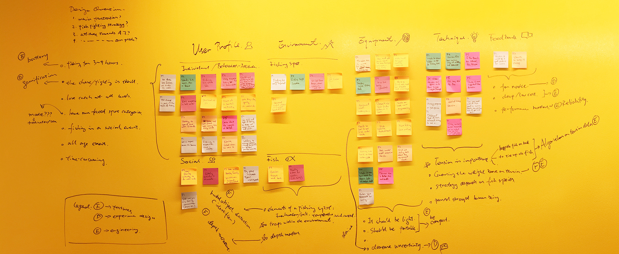
User Research
The team conducted a user research session to understand the fishers’ need better and seek for possible solutions. Interviews and survey were used to study the subject matter in attitudinal, qualitative and quantitative ways.
Interviews
Remote interview with a fishing hobbyist.
Research questions:
What are the main frustrations for a fishing hobbyist? What causes these frustrations?
Is there any fish-fighting strategy recommended by the fishers?
What is the attitude of the fishing hobbyists towards assistive technology for fishing?
What is the opinion of the interviewees on our lab work product—the smart fishing rod?
Surveys
Research questions:
What is the demographic pattern of the fisher group?
What are the fishers’ attitude towards assistive technologyfor fishing?
What are the techniques recommended by a fisher to fight ahooked fish?
Product Requirements
Based on the findings from the User Research session, the team extracted the product requirements.
Product Feature
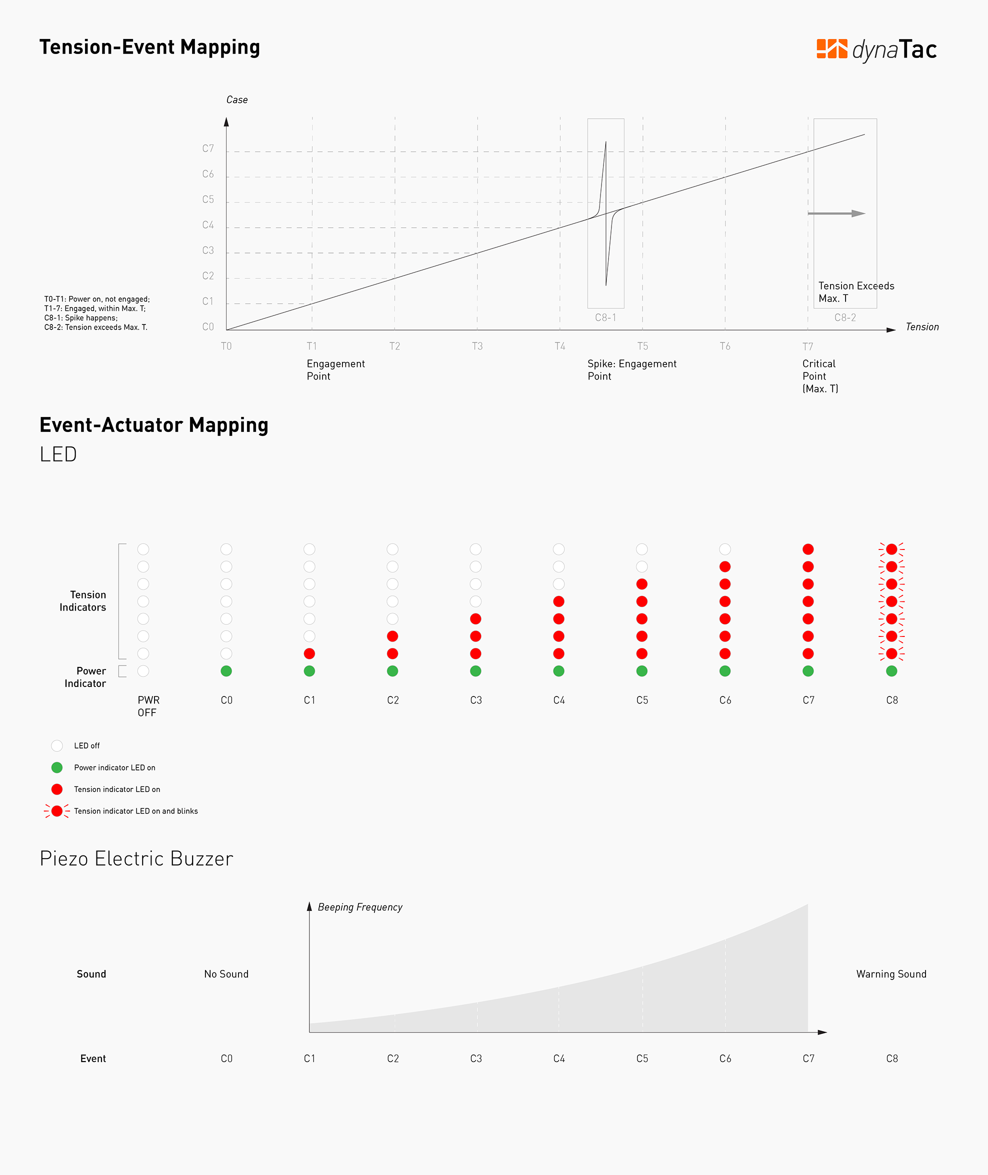
Tension indicator;
Strategy indicator based on tension.
Experience Design
Must be able to convey—1. The tension and 2. the fighting strategy in any scenario (e.g., under strong sunlight);
Gamification: the design should be intuitive and exciting.
Engineering
It should be lightweight;
Battery life: 3-4 hours;
Able to detect spikes in tension;
Audio/visual/haptic feedback is necessary.
Sensing Methods Explored
M1
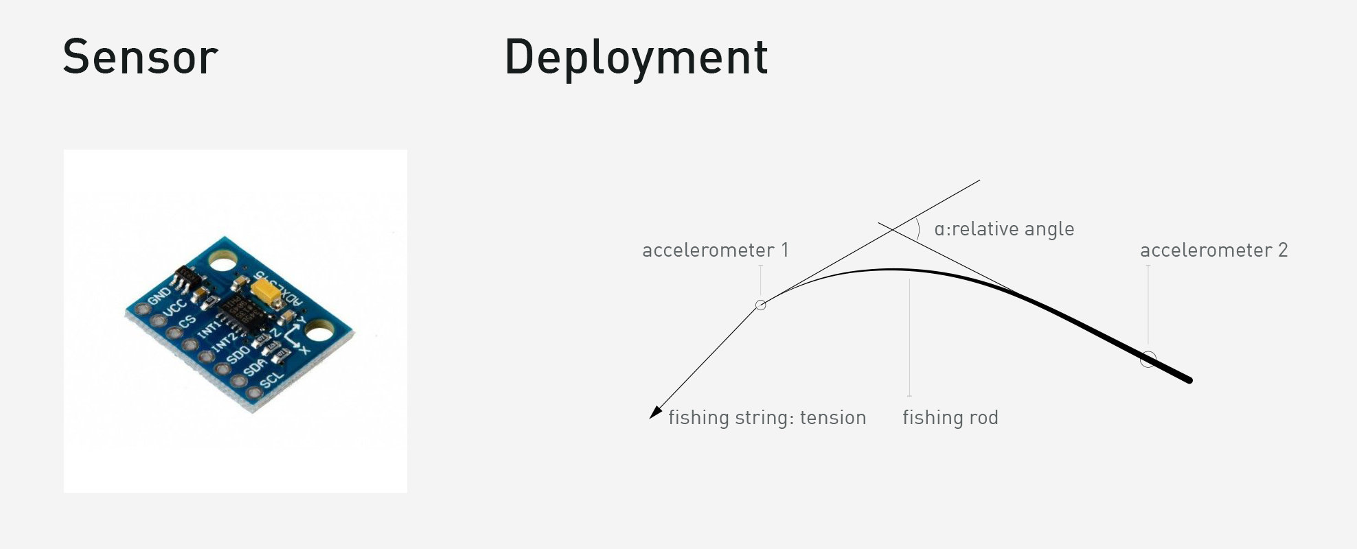
Accelerometer
The first method (M1, so forth) tried by the team was using an accelerometer pair to measure the angle between the tip and the base of the fishing rod. The angle can be used to compute tension value. Tension = f(α).
Decision and Rationale
The team tried this method, and it was promising, but not user- friendly because it would require mounting devices on both the tip and the base of the fishing rod. The mounting solution would be obtrusive and harmful to the fishing experience. In the meantime, this method had some logic defects. So the team did not choose it.
M2
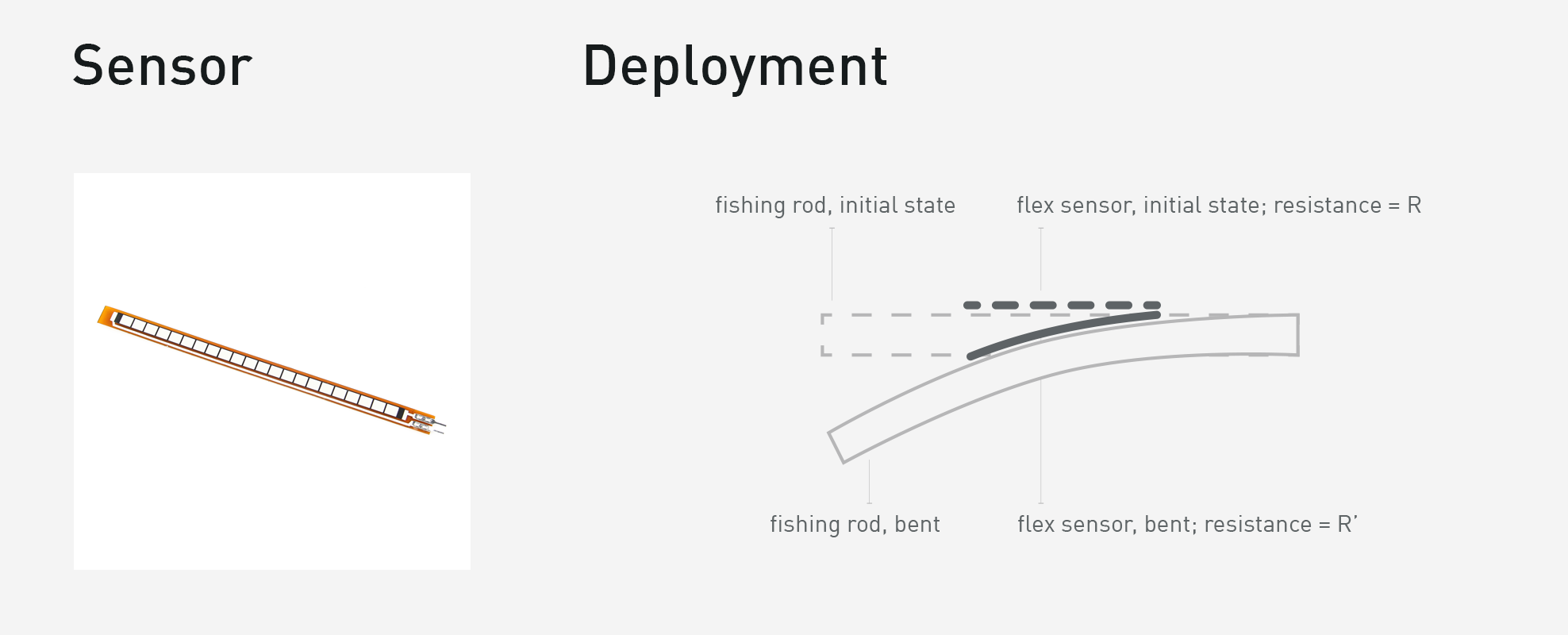
Flex Sensor
The M2 been tried was to detect the deflection of the tip by taping a flex sensor to the tip of the rod. This method is similar to M1. Both used Young’s Modulus of the fishing rod and the level it bent to estimate the tension.
Decision and Rationale
M2 had the similar disadvantage with M1, it required installations on both ends, and the connection between two parts make it undesirable for a fisher.
M3
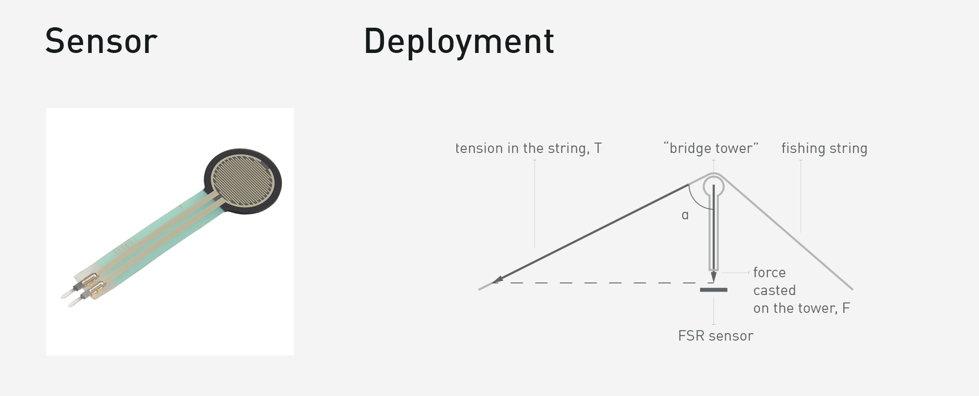
FSR Sensor
The M3 was to detect the tension in the fishing string by using a bridge-tower-like structure to decompose the tension in the string to a vertical conductor that touches the FSR sensor. T = F / cosα.
Decision and Rationale
This method required some initial physical model design to get it to work, but even with a very primitive model, the team had good results using this method. They proceeded with this method for the rest of the quarter.
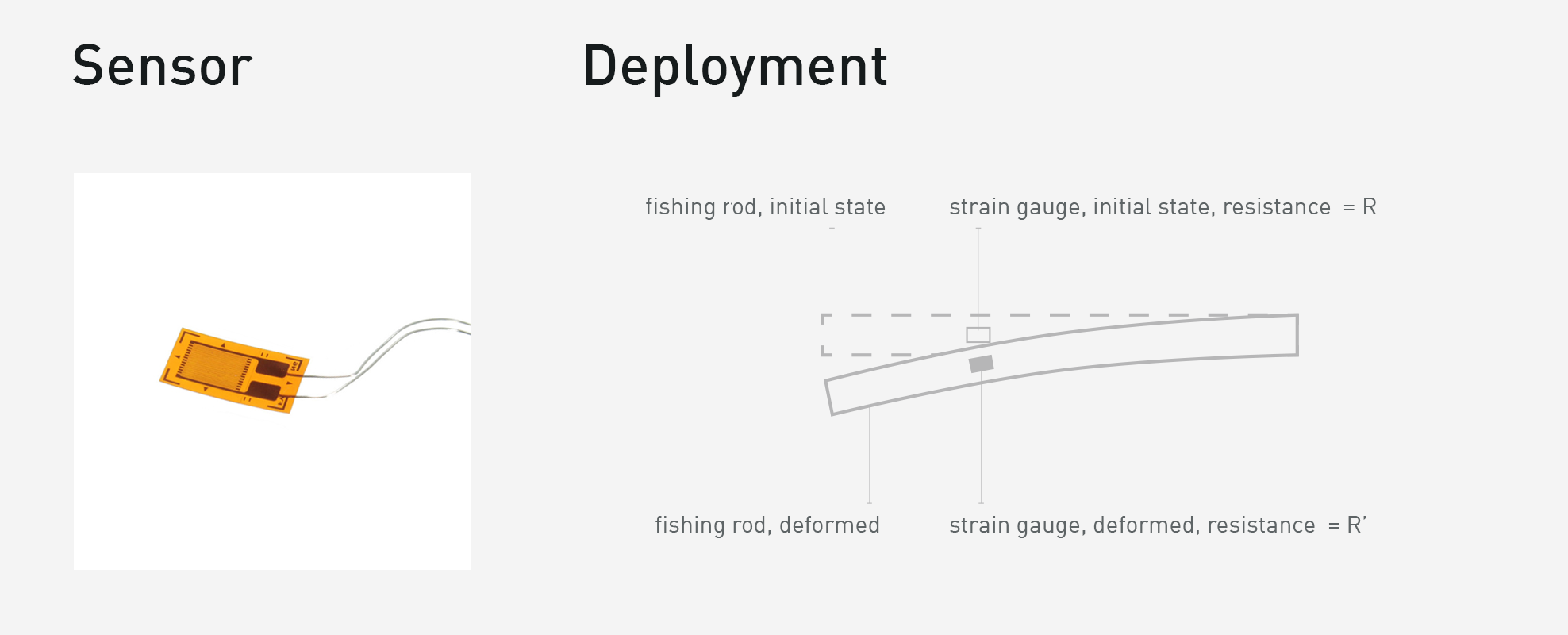
M4
Strain Gauge
The last method had been tried was to detect the force applied to the rod by using a strain gauge sticked on the surface of
the rod. Tiny deformation of the rod can be captured, and its extent is an indicator of tension.
Decision and Rationale
The team tried this method and were able to get promising results at first, but there would need to be a significant investment of time to make it work reliably, so it was not chosen.
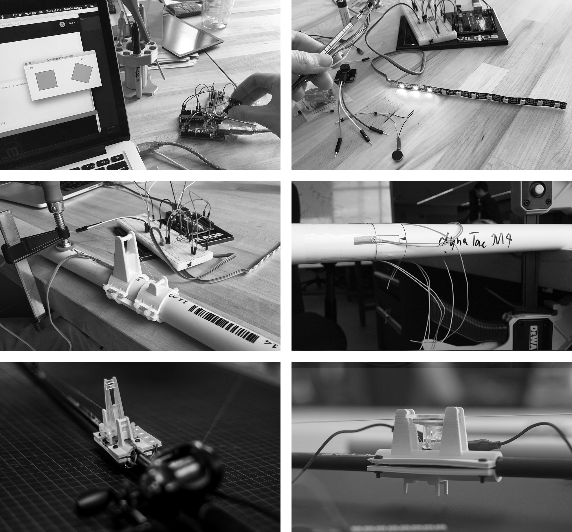
Prototypes
M1P1–M3P3
A series of prototypes were fabricated to test four sensing methods. After the first round of prototyping (P1), the team chose M3—FSR sensor bridge tower—to continue iteration. M3P2, M3P2 were prototyped to evolve the solution. A conceptual M3P4 were explored in the sketch.
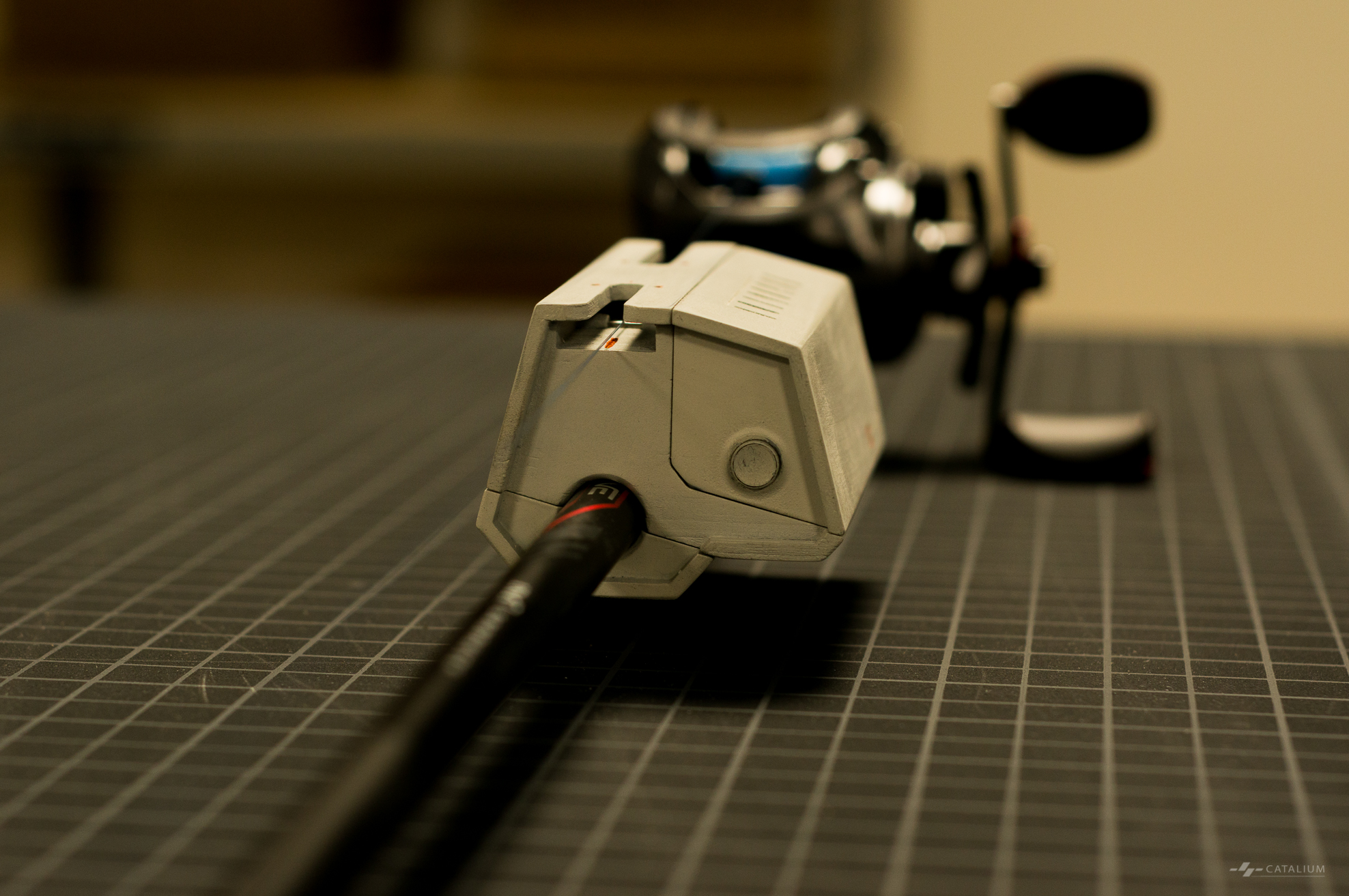
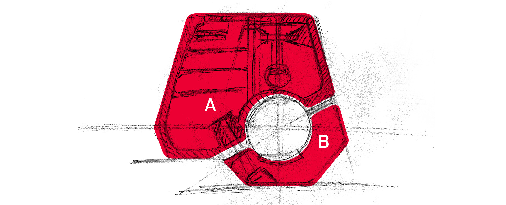
M3P5
Framework
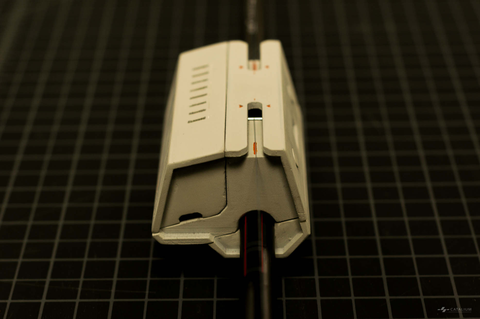
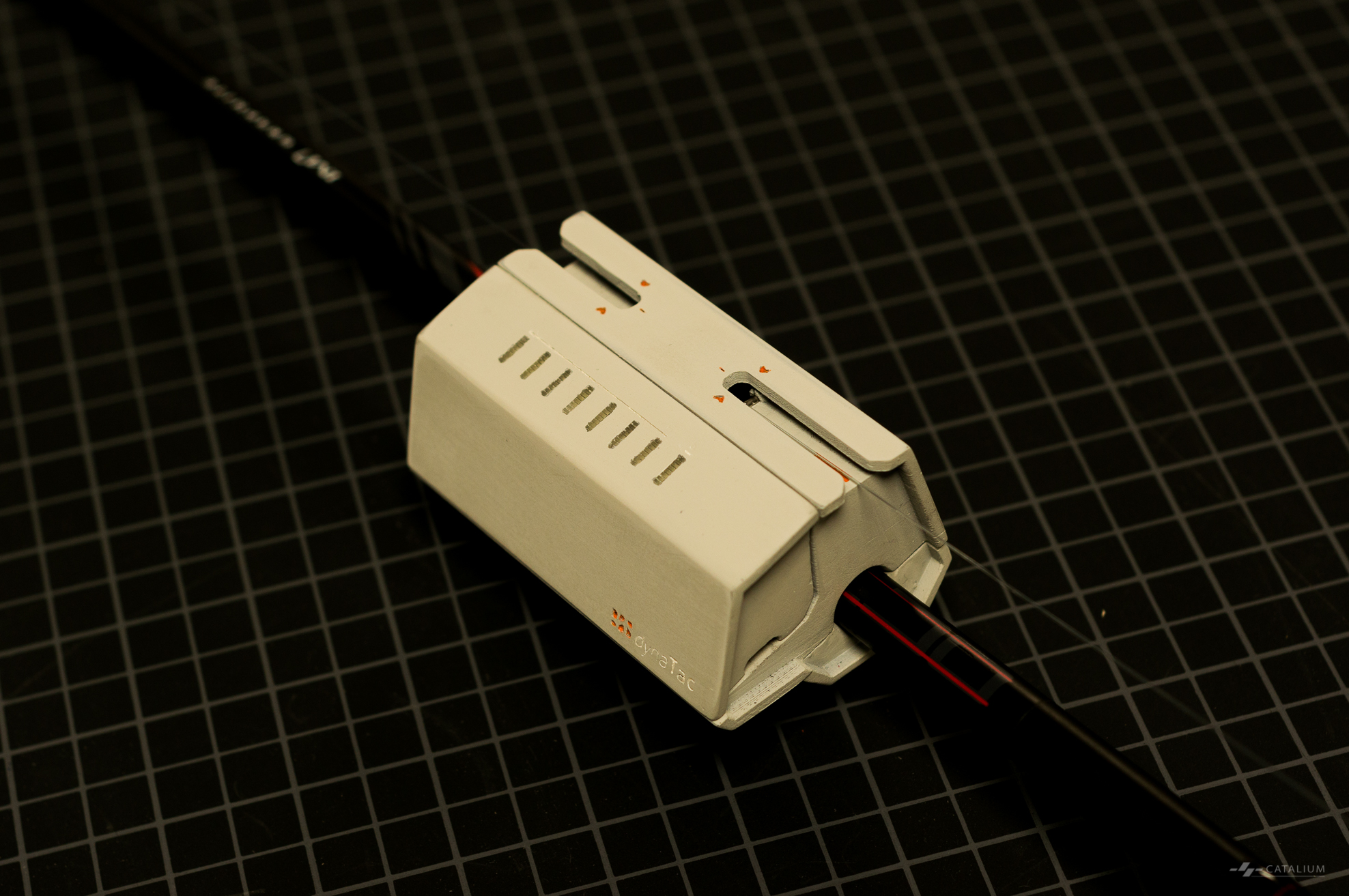
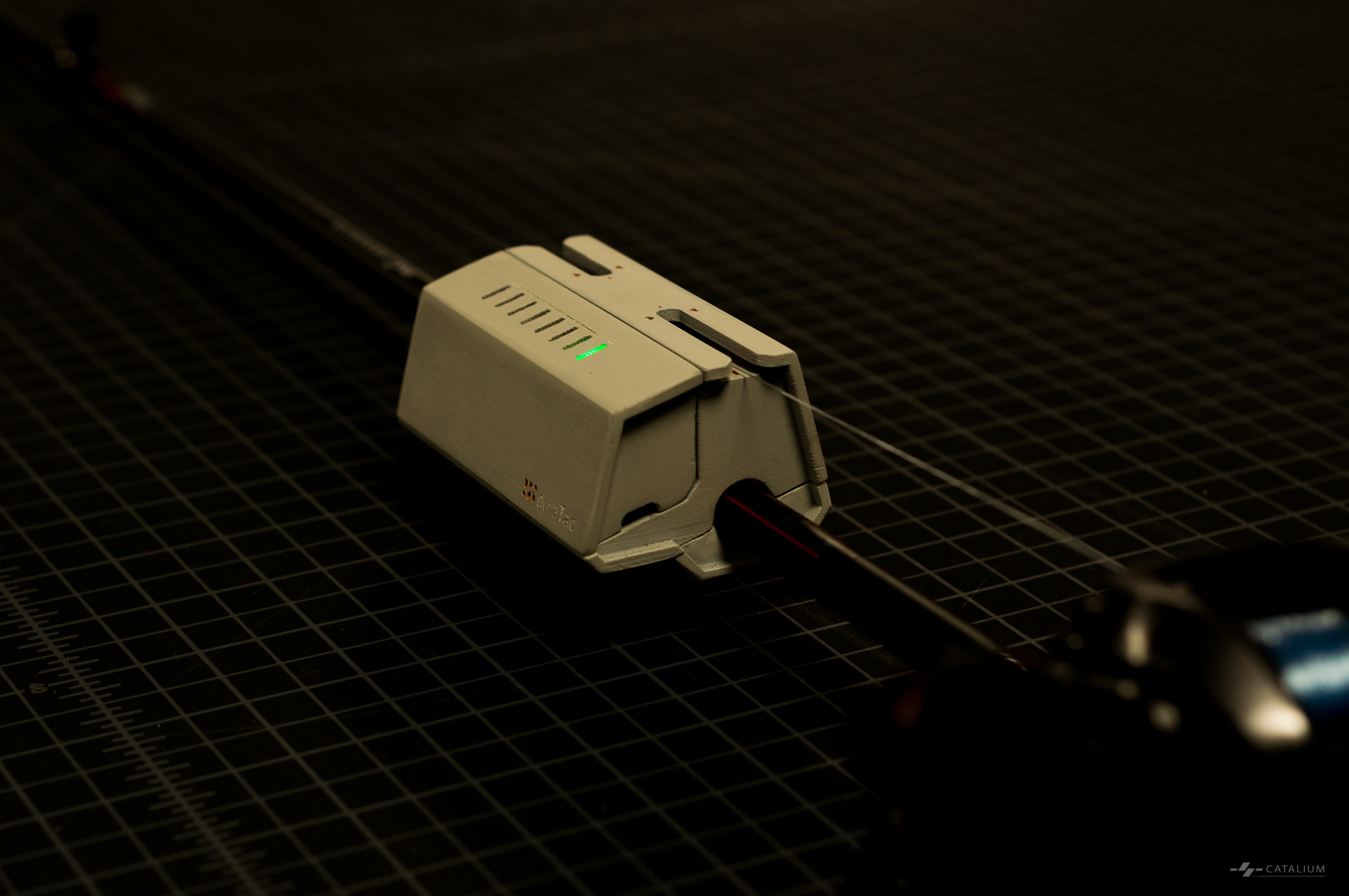
I invented the M3P5 that could enclose all components in a compact body and yet were easy to install. Instead of having clam shell-like two parts, M3P5 had four sections: three parts formed the upper part — A, which had two chambers—one for mechanic components, one for electronic components; the remaining portion — B, was only used to mount the device.
Grooves were designed to hold rubber pieces as the cushioning material, with rubber Young’s Modulus coefficient taken into consideration.
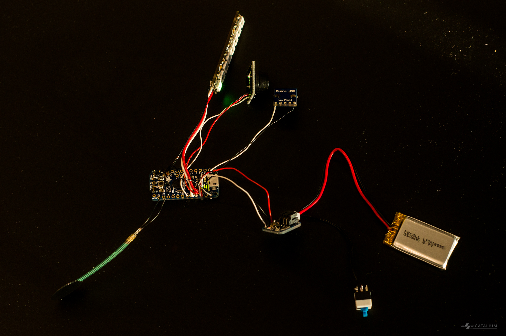
Electronics
Circuitry designed by Maksim, prototyped by Maksim and Tyson. The circuitry can fulfill requirements of the final prototype.
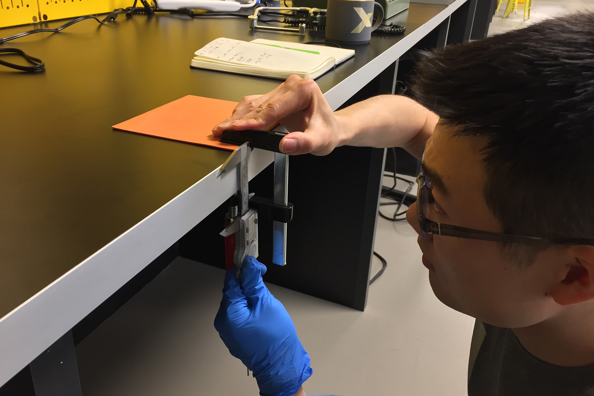
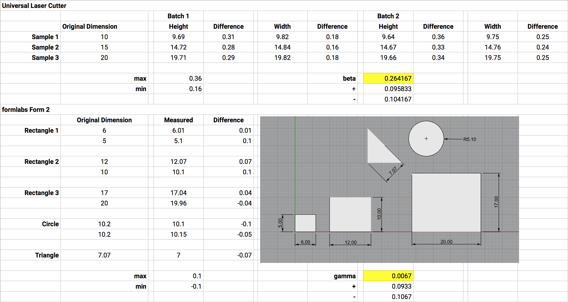
CAD
Before building the CAD model, the team measured the tolerance for fabrication tools. The data was used to leave proper tolerance when modeling in CAD environment.
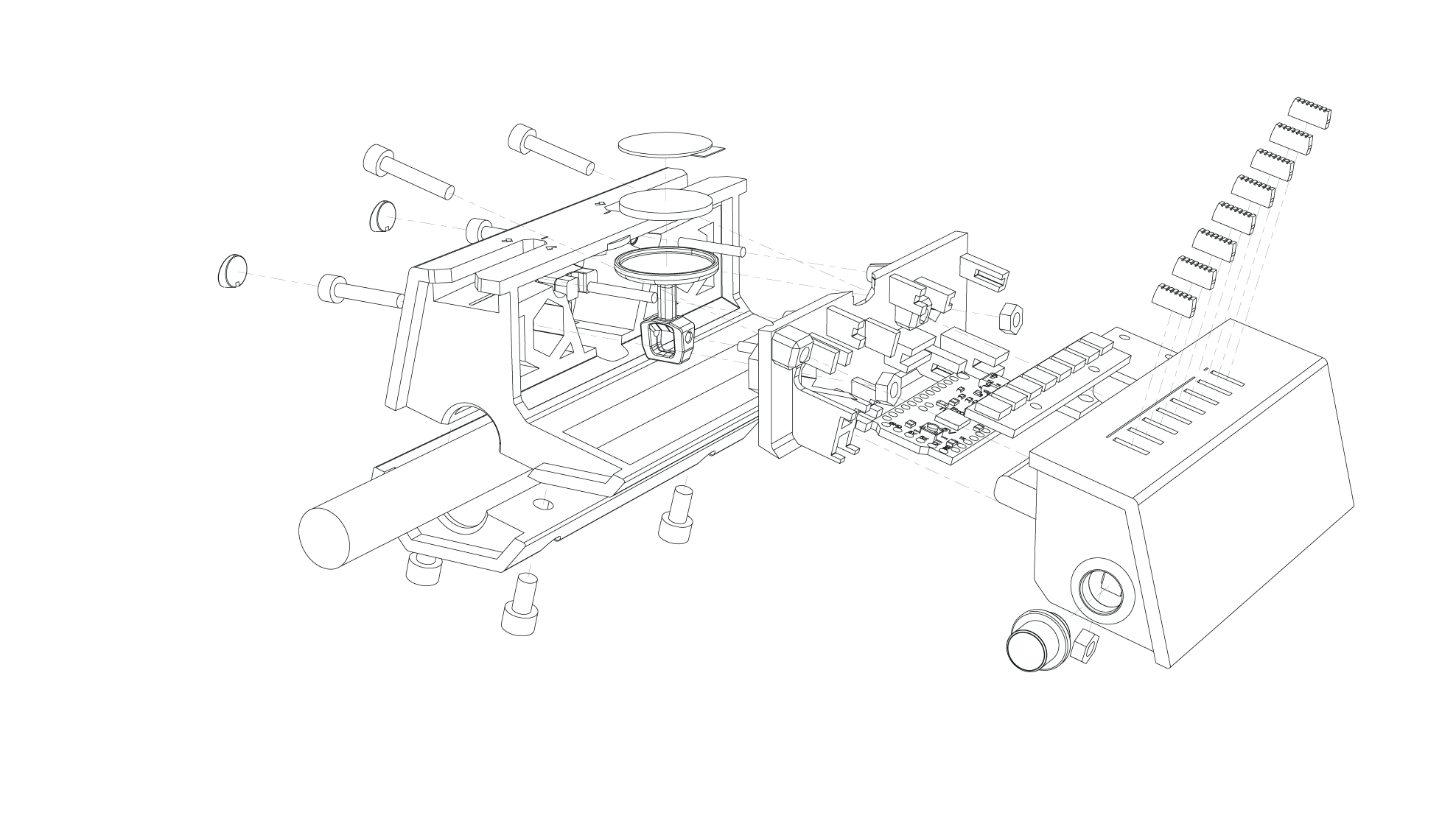
Explosion view of the dynaTac final design.
Fabrication
I used two 3D printers to fabricate the parts with three materials: a StrataSys F170 printed part A-1 with ABS, a Formlabs Form 2 printed A-2, A-3, and B with white photopolymer resin, and LED light guide with clear photopolymer resin.
Finishing
Post script: an artwork based on the explosion view of dynaTac was given to Brad Smith, the president of Microsoft, as the present from GIX after the commencement ceremony on December 9th, 2018.

 Background
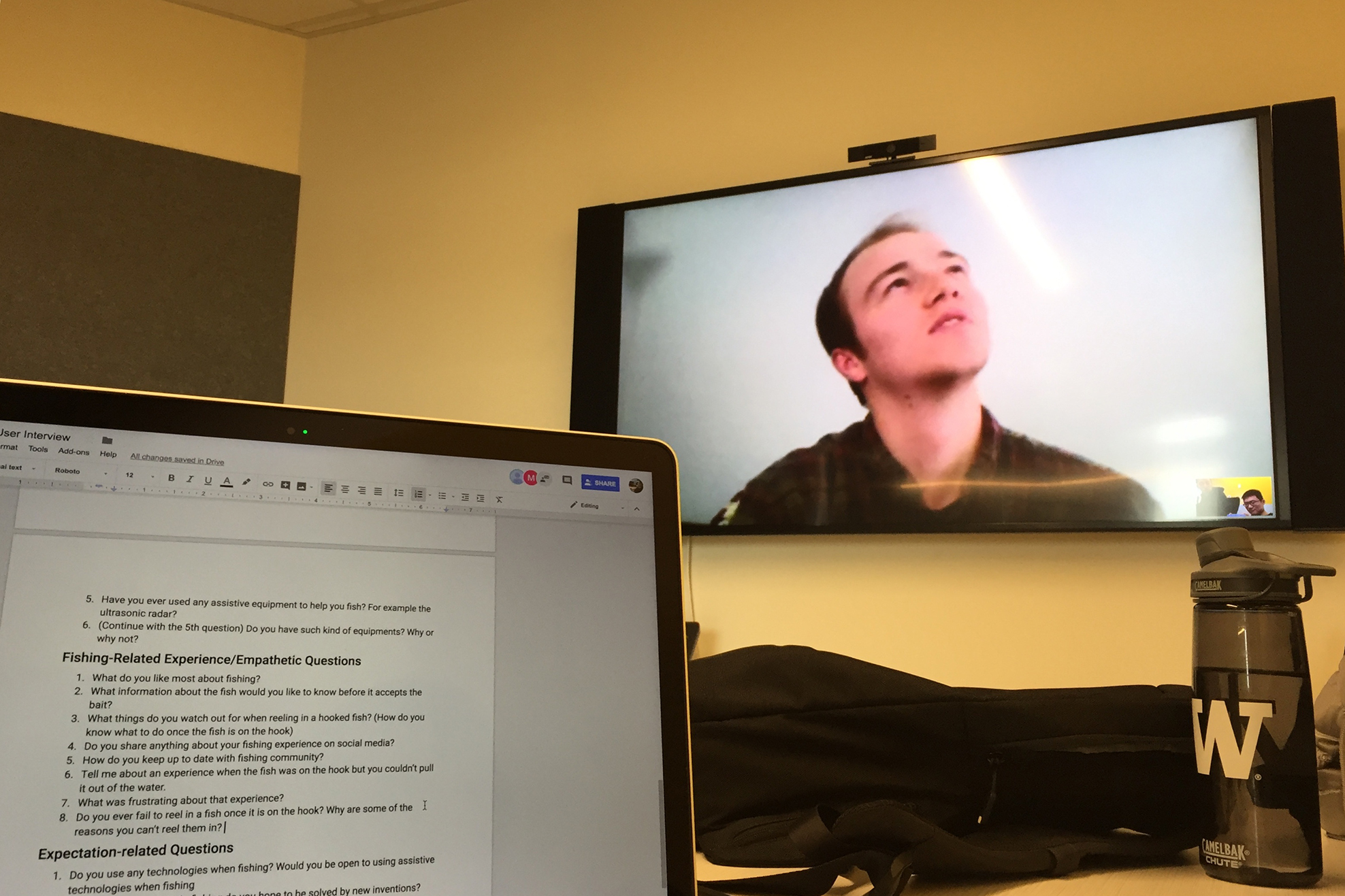
 Based on the findings from the User Research session, the team extracted the product requirements.
 A series of prototypes were fabricated to test four sensing methods. After the first round of prototyping (P1), the team chose M3—FSR sensor bridge tower—to continue iteration. M3P2, M3P2 were prototyped to evolve the solution. A conceptual M3P4 were explored in the sketch.
 I invented the M3P5 that could enclose all components in a compact body and yet were easy to install. Instead of having clam shell-like two parts, M3P5 had four sections: three parts formed the upper part — A, which had two chambers—one for mechanic components, one for electronic components; the remaining portion — B, was only used to mount the device.
 Grooves were designed to hold rubber pieces as the cushioning material, with rubber Young’s Modulus coefficient taken into consideration.
 Circuitry designed by Maksim, prototyped by Maksim and Tyson. The circuitry can fulfill requirements of the final prototype.
 Before building the CAD model, the team measured the tolerance for fabrication tools. The data was used to leave proper tolerance when modeling in CAD environment.
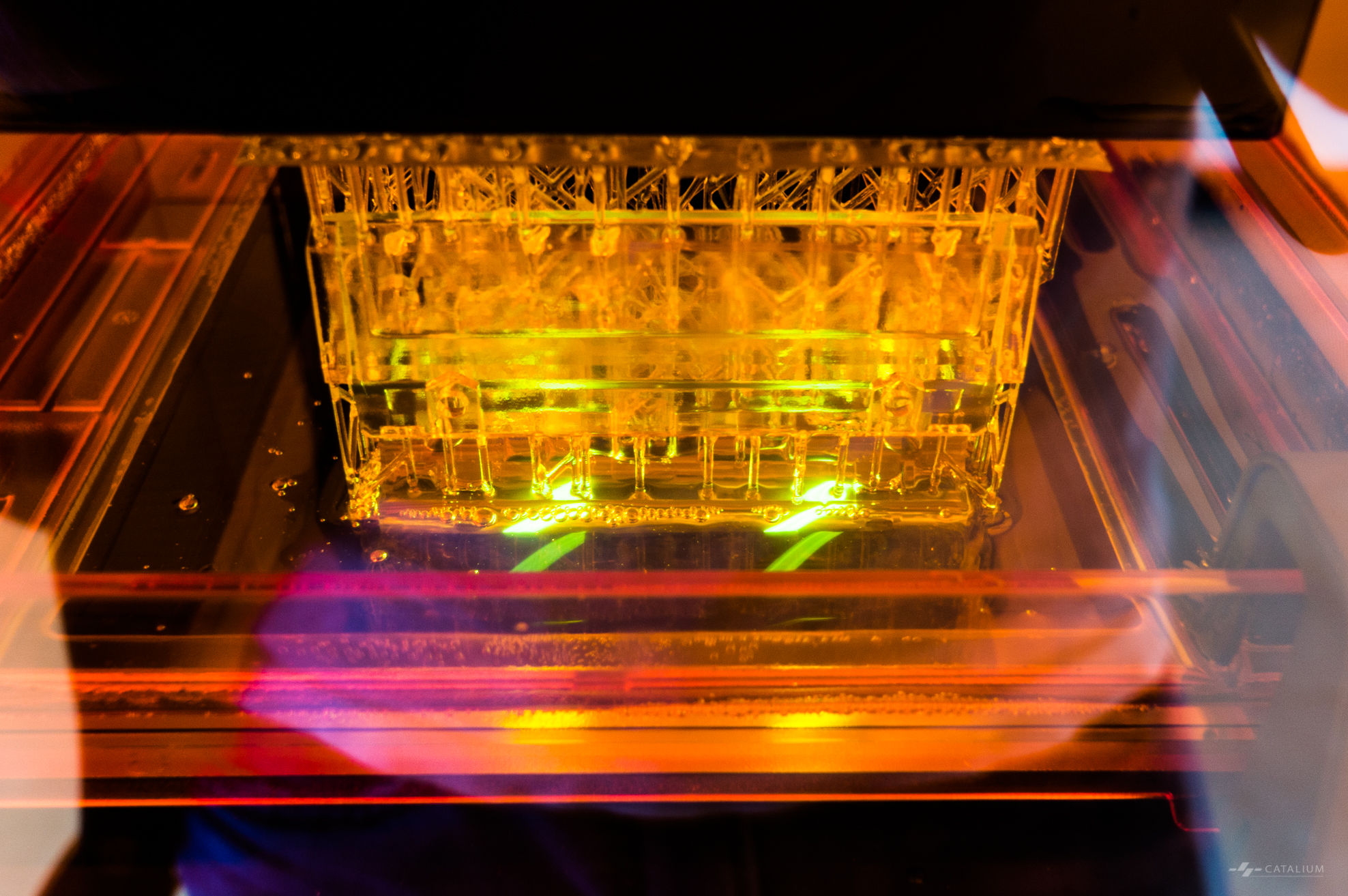
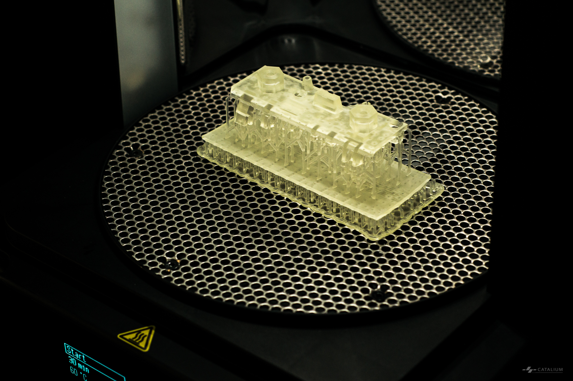
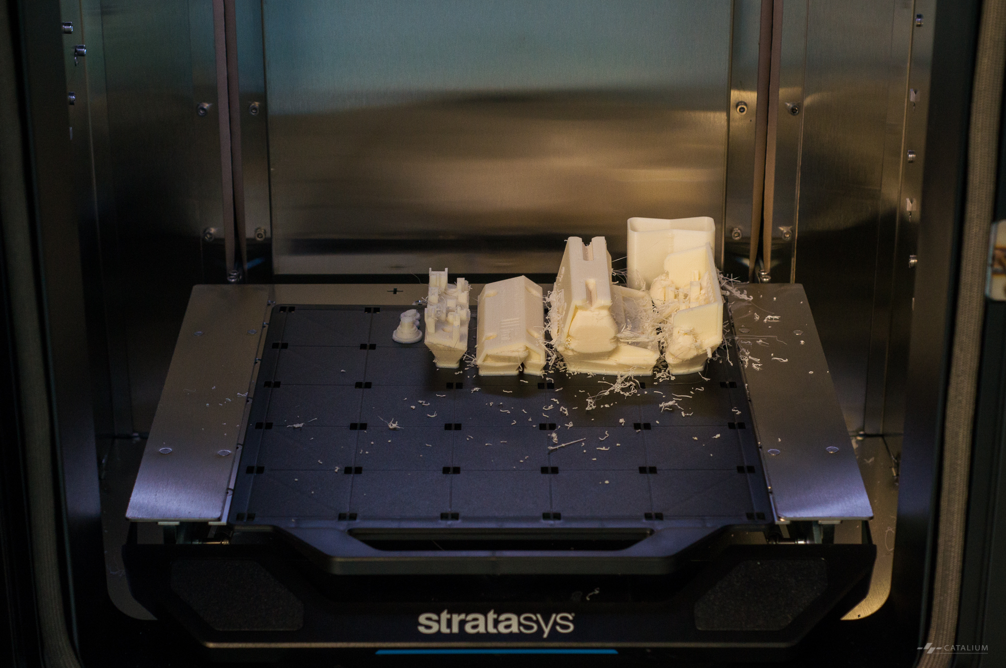 I used two 3D printers to fabricate the parts with three materials: a StrataSys F170 printed part A-1 with ABS, a Formlabs Form 2 printed A-2, A-3, and B with white photopolymer resin, and LED light guide with clear photopolymer resin.